- human optics. As we see ……………………………………… ..2-3
- Visual impairments ………………………………………………………… .3-5
- Optical devices, "arming" the eye. Glasses, magnifier, microscope, telescope ………………………………………………………… 5-11
- Svetoprektsionnaya technique. Projection devices, spectral apparatus, camera, movie camera ...… ..11-16
- Conclusion ……………………………………………………………………… ..17
- References ……………………………… .18
Human optics
As we see
Human eyes are the eyes, which in many ways are a very advanced optical system.
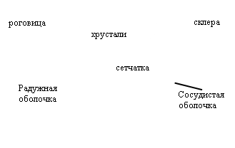 In general, the human eye is a spherical body with a diameter of about 2.5 cm, which is called the eyeball (Fig.5). The opaque and durable outer shell of the eye is called the sclera, and its transparent and more convex front part is called the cornea. The inner side of the sclera is covered with a choroid, consisting of blood vessels that feed the eye. Against the cornea, the choroid enters the iris, which is not uniformly colored in different people, which is separated from the cornea by a chamber with a transparent aqueous mass.
The iris has a circular opening called the pupil, the diameter of which may vary. Thus, the iris plays the role of the diaphragm, which regulates the access of light to the eye. In bright light, the pupil decreases, and in low light it increases. Inside the eyeball behind the iris is the lens, which is a biconvex lens of a transparent substance with a refractive index of about 1.4. The lens borders the annular muscle, which can alter the curvature of its surfaces, and hence its optical power.
The choroid on the inner side of the eye is covered with branches of the photosensitive nerve, especially thick opposite the pupil. These branches form a reticular membrane, on which a real image of objects is created, created by the optical system of the eye. The space between the retina and the lens is filled with a transparent vitreous body, which has a gelatinous structure. The image of objects on the retina turns upside down. However, the activity of the brain, receiving signals from the light-sensitive nerve, allows us to see all the objects in natural positions.
When the annular muscle of the eye is relaxed, the image of distant objects is obtained on the retina. In general, the device of the eye is such that a person can see without stress objects that are located no closer than 6 meters from the eye. The image of closer objects in this case is obtained behind the retina. To obtain a clear image of such an object, the ring muscle squeezes the lens more and more until the image of the object is on the retina, and then keeps the lens in a compressed state.
Thus, the "focus on focus" of the human eye is carried out by changing the optical power of the lens with an annular muscle. The ability of the optical system of the eye to create distinct images of objects that are located at different distances from it is called accommodation (from the Latin “accommodation” is a device). When viewing very distant objects, parallel rays enter the eye. In this case, it is said that the eye is adapted to infinity.
The accommodation of the eye is not infinite. With the help of the ring muscle, the optical power of the eye can increase by no more than 12 diopters. With a long examination of close objects, the eyes get tired, and the annular muscle begins to relax and the image of the object blurs.
Human eyes allow you to see things well, not only in daylight. The ability of the eye to adapt to varying degrees of irritation of the endings of the photosensitive nerve on the retina, i.e. to varying degrees of brightness of the observed objects is called adaptation.
The reduction of the visual axes of the eyes at a certain point is called convergence. When objects are located at a considerable distance from a person, when the eye is transferred from one object to another, between the axes of the eyes practically does not change, and the person loses the ability to correctly determine the position of the object. When objects are very far away, the axis of the eyes are parallel, and the person cannot even determine whether the object is moving or not, which he is looking at. A certain role in determining the position of the bodies is played by the force of the annular muscle, which compresses the lens when viewing objects located close to a person.
Eye defects
Myopia.
If the distance between the retina and the lens is abnormally large or the lens is so rounded and thick that its focal length is abnormally small, the image of the removed object falls in front of the retina (Fig. 4). This eye defect is very common and is called myopia or myopia. Myopia is an eye defect that is extremely common among schoolchildren and students. According to specialists, every 3 births out of 100 have this defect; in elementary school, the number of myopic is about 10 out of 100; in middle school the number of myopic people reaches 24%, and in college - 31%. Among the wild tribes living and working mostly outdoors, myopia is almost unknown. Similarly, among farmers and those working outdoors, a very small number suffer from myopia, unless they have acquired it at school or when working with close objects.
The cause of myopia in most cases is, apparently, the fact that in childhood the eye is easily deformed. When working with similar objects, the eyeball “gets used” to lengthen so much that the lens already loses its ability to flatten itself to focus the image of a distant object on the retina without excessive tension. Compare the length of the myopic eye in fig. 4 with a long-sighted length in fig. five.
Myopia test .
One type of check for myopia is done using the Snellen table. The Snellen table in a reduced form is shown in Fig. 5. Under normal vision, you can read the seventh line of a well-lit standard size table with each eye separately with a distance of 50 cm. Failure to do this does not necessarily indicate myopia, since this immediacy may be due to another reason. But if a negative (diffusing) spherical lens improves visibility (in this case, you need to start with a lens of low optical power and gradually increase the power of the lens), then you can assume the presence of myopia.
Myopia can be corrected, but not cured, with the help of glasses. In this case, spherical lenses are used (Fig. 4.c). This lens scatters parallel light wave beams, which emanate from distant objects sufficiently so that the image falls on the retina beyond the place where it would be without the use of glasses.

Hyperopia, or hyperopia .
If the distance between the retina and lens is abnormally small or if the lens is abnormally thin and flattened, so that its focal length is abnormally long, then the image of close objects is behind the reticular membrane (Fig. 6). Therefore, close objects cannot be seen without straining the eyes.
If you are only far-sighted and have no other visual impairments, then you can easily read the 9th line of the Snellen table, but your near point may be further than your normal position.
To correct hyperopia, reduce the image distance for close objects. This requires the use of a collective (positive) lens of appropriate optical power.
Astigmatism.
Usually, the surface of the cornea — a slightly protruding anterior part of the eyeball — and the surface of the lens are parts of almost perfect spheres. However, often the curvature of one or both of these surfaces is greater in one plane than in any other. This defect, which results in fuzzy vision, is called astigmatism.
Astigmatism can cause headaches and create vagueness, especially if you read for a long time in a row. Astigmatism is corrected by a cylindrical lens instead of a spherical lens. Note, in particular, that the direction of curvature of the lens of glasses must coincide with the corresponding curvature of the eye lens. Therefore, if the astigmatic lens changes its position relative to the eye, it is necessary to take measures to bring it back into place, since it is absolutely necessary that the corresponding curvatures coincide.
Optical devices that equip the eye
Glasses
Who invented the magnifying glass?
If we leave aside the fragmentary data, which date back to ancient times, the magnifying glasses became the object of scientific consideration already in the era of the early Middle Ages. Alhazen also investigated the magnification created by the glass sphere, viewing it as an optical illusion. Later, glasses appeared that could not be the result of theoretical consideration, for it is impossible to imagine that with the medieval theory of vision one could even come to the idea of the possibility of correcting his defects. This discovery was probably accidental, and it is likely to assume that it was written by someone from the glass makers.
The fact that this discovery was made by artisans is confirmed by the folk origin of the word "lente" (lens) from the word "lenticchia" (lentils), which the scientists of the 16th century decided to refine somewhat by romanizing it.
For the first time lenses for the purposes of science applied Bacon. It is known that he used them in many experiments and even offered one to Pope Clement IV, asking him to try to apply it. Bacon avoids the special name and speaks of "adaptation." Even in the 16th century, Jerome Cardan, always a vaguely Latin-speaking man, calls lenses "orbem e vitro" - an expression that his French translator either did not understand, or could not correctly express in French and directly translated "rotondite faite du verre" ( roundness made of glass).
For three centuries after Bacon in the writings of scientists it was impossible to find references to "glasses for old ones", as biconvex glasses were called, or "glasses for young people" - biconcave glasses for correcting myopia.
Biconcave glass appeared, obviously, later biconvex and also, apparently, by chance were invented by glaziers-masters or were the result of elementary reasoning: if bulging glasses help the old people see, the concave ones should, on the contrary, help the eyesight of the young. By the middle of the 14th century, glasses were already widely spread - a 1352 monk with glasses was depicted on a fresco.
In 1743, the French naturalist Buffon Georges Louis Leclerc suggested an occlusion (Latin occlusio - locking, hiding) of a healthy eye in order to correct strabismus and restore visual acuity of the sore eye. This method is used now.
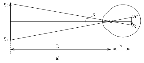
Although the eye does not constitute a thin lens, one can still find in it a point through which the rays pass practically without refraction, i.e. point playing the role of the optical center. The optical center of the eye is located inside the lens near its back surface. The distance h from the optical center to the retina, called the depth of the eye, is 15 mm for a normal eye.
Knowing the position of the optical center, you can easily build an image of an object on the retina of the eye. The image is always valid, reduced and inverse. The angle φ at which the object S1S2 from the optical center O is visible is called the angle of view.
The mesh shell has a complex structure and consists of individual light-sensitive elements. Therefore, two points of an object that are so close to each other that their image on the retina falls into the same element are perceived by the eye as one point. The minimum angle of view, at which two luminous points or two black points on a white background are perceived by the eye still separately, is approximately one minute. The eye does not recognize the details of the object, which it sees at an angle of less than 1. "This is the angle at which a segment is visible, the length of which is 1 cm at a distance of 34 cm from the eye. In poor light (at dusk), the minimum resolution angle rises and can reach 1º .
 |
|||
By bringing the subject to the eye, we increase the angle of view and, therefore, we get
the ability to better distinguish small details. However, we cannot bring them very close to the eye, since the ability of the eye to accommodate is limited. For a normal eye, the most favorable for viewing an object is a distance of about 25 cm, at which the eye can distinguish details quite well without excessive fatigue. This distance is called the best view distance. For a myopic eye, this distance is somewhat shorter, so myopic people, placing the object in question closer to the eye than people with normal vision or far-sighted, see it from a large angle of view and can better distinguish small details.
A significant increase in the angle of view is achieved with the help of optical devices. According to their purpose, optical devices, arming the eye, can be divided into the following large groups.
1. Instruments used to examine very small objects (magnifier, microscope). These devices "increase" the objects in question.
2. Instruments intended for viewing distant objects (telescope, binoculars, telescope, etc.). These devices "approach" the objects in question.
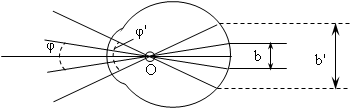
By increasing the angle of view when using an optical device, the size of the image of an object on the retina increases in comparison with the image in the naked eye and, consequently, the ability to recognize parts increases. The ratio of the length b on the retina in the case of an armed eye b "to the length of the image for the unaided eye b (Fig.11, b) is called the increase in the optical device.
Using pic. 11, b it is easy to see that the increase in N is also the ratio of the angle of view φ "when viewing an object through the tool to the angle of view φ for the naked eye, for φ" and φ are small.
N = b "/ b = φ" / φ,
where N is the increase in the subject;
b "- the length of the image on the retina for the armed eye;
b - the length of the image on the retina for the naked eye;
φ "- angle of view when viewing an object through an optical instrument;
φ - the angle of view when viewing the subject with the naked eye.
Magnifier
One of the simplest optical devices is a magnifying glass - a collecting lens designed for viewing enlarged images of small objects. The lens is brought to the eye, and the object is placed between the lens and the main focus. The eye will see an imaginary and enlarged image of the object. It is most convenient to view the object through a magnifying glass with a completely unstressed eye, accommodated for infinity. To do this, the object is placed in the main focal plane of the lens so that the rays emanating from each point of the object form parallel beams behind the lens. In fig. 12 depicts two such beams coming from the edges of the object. Getting into the eyes, which are adapted to infinity, beams of parallel rays focus on the retina and give here a clear image of the object.
 |
Angle magnification. The eye is very close to the lens, so the angle of view can be taken as an angle of 2γ, formed by rays coming from the edges of the object through the optical center of the lens. If there were no magnifying glass, we would have to place the object at a distance of the best view (25 cm) from the eye and the angle of view would be 2β. Considering right-angled triangles with legs 25 cm and F cm and denoting half of the object Z, we can write:
![]() ,
,
where 2γ is the angle of view, when observed through a magnifying glass;
2β - the angle of view, when observed with the naked eye;
F is the distance from the object to the magnifier;
Z - half the length of the subject.
Taking into account that usually small details are considered through a magnifying glass and therefore the angles γ and β are small, it is possible to replace the tangents with angles. Thus, we get the following expression to increase the loop = =.
Therefore, the magnification of a magnifying glass is proportional to 1 / F, that is, its optical power.
Microscope.
A device that allows you to get a big increase when looking at small objects is called a microscope.
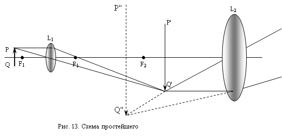
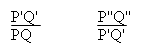
The simplest microscope consists of two collecting lenses. The very short-focus lens L1 gives a greatly enlarged real image of the object P "Q" (Fig. 13), which is viewed by the eyepiece as a magnifying glass.
 |
|||||
 |
|
||||
Denote the linear magnification given by the lens as n1, and with the eyepiece n2, this means that = n1 and = n2,
where P "Q" is an enlarged real image of the object;
PQ - the size of the subject;
Multiplying these expressions, we get = n1 n2,
where PQ is the size of the subject;
P "" Q "" - enlarged imaginary image of the object;
n1 - linear increase of the lens;
n2 - linear increase in the eyepiece.
This shows that the magnification of a microscope is equal to the product of the magnifications given by the objective and the eyepiece separately. Therefore, it is possible to build tools that give very large increases - up to 1000 or even more. In good microscopes, the objective and the eyepiece are complex.
An eyepiece usually consists of two lenses; the lens is much more complicated. The desire to get large increases make you use short-focus lenses with very high optical power. The object under consideration is placed very close to the lens and gives a wide beam of rays that fills the entire surface of the first lens. Thus, very unfavorable conditions are created for obtaining a sharp image: thick lenses and off-center rays. Therefore, to correct all sorts of shortcomings, it is necessary to resort to combinations of many lenses of different types of glass.
In modern microscopes, the theoretical limit is almost reached. Very small objects can also be seen in a microscope, but their images are represented as small specks that have no similarity with the object.
When examining such small particles, they use the so-called ultramicroscope, which is a conventional microscope with a condenser, which makes it possible to intensely illuminate the object in question from the side, perpendicular to the axis of the microscope.
With the help of an ultramicroscope, it is possible to detect particles whose size does not exceed microns.
Telescope (Telescopes)
The simplest telescope consists of two collecting lenses. One lens facing the subject in question is called an objective, and the other facing the eye of the observer is called an eyepiece.
Lens L1 gives the actual reverse and strongly reduced image of the subject P1Q1, lying near the main focus of the lens. The eyepiece is placed so that the image of the object is in its main focus. In this position, the eyepiece plays the role of a magnifying glass, with which the actual image of the object is examined.

The action of the pipe, like the magnifying glass, is reduced to an increase in the angle of view. With the help of a pipe, objects are usually considered that are at distances that are many times longer than its length. Therefore, the angle of view, under which the object is visible without a pipe, can be taken angle 2β formed by the rays coming from the edges of the object through the optical center of the lens.
The image is seen at an angle of 2γ and lies almost at the very focus of the lens F and in the focus F1 of the eyepiece.
Considering two right-angled triangles with a common side Z ", we can write:
![]() ,
,
2β - the angle of view, under which the object is visible to the naked eye;
F - Lens focus;
F1 - eyepiece focus;
Z "- half the length of the subject.
The angles β and γ are not great, therefore it is possible with sufficient approximation to replace tgβ and tgγ with angles and then the increase in the pipe = 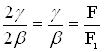 ,
,
where 2γ is the angle from which the image of the object is visible;
2β - the angle of view, under which the object is visible to the naked eye;
F - Lens focus;
F1 - focus eyepiece.
The angular magnification of the tube is determined by the ratio of the focal length of the lens to the focal length of the eyepiece. To get a big zoom, you need to take a long-focus lens and a short-focus eyepiece.
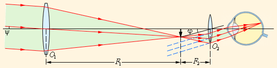
Figure 14
Telescopic beam path.
Lighting projection equipment
Projection devices.
A projection apparatus is used to show viewers on the screen of an enlarged image of drawings, photographs or drawings. Drawing on glass or on a transparent film is called a slide film, and the device itself, designed to display such drawings, is called a diascope. If the device is designed to display opaque paintings and drawings, then it is called an episcopate. The device designed for both cases is called an epidiascope.
A lens that creates an image of an object in front of it is called a lens. Usually the lens is an optical system, which eliminated the major shortcomings inherent in individual lenses. In order for the image of the subject to be clearly visible to the audience, the subject itself must be brightly lit.
The layout of the projection apparatus is shown in Figure 16.
The light source S is placed in the center of the concave mirror (reflector) R. light coming directly from the source S and reflected from the reflector R, falls on the condenser K, which consists of two plane-convex lenses. The condenser collects these light rays on
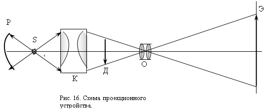
the lens ABOUT, which already directs them to the screen Uh where is the image of the slide D. Slide itself is placed between the main focus of the lens and a point located at a distance 2 F from the lens. The sharpness of the image on the screen is achieved by moving the lens, which is often called focusing.
Spectral devices.
To observe the spectra using a spectroscope.
The most common prismatic spectroscope consists of two tubes, between which a three-sided prism is placed (Fig. 17).
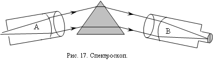
In tube A, called the collimator, there is a narrow slit, the width of which can be adjusted by turning the screw. In front of the slit is placed a light source whose spectrum is to be investigated. The slit is located in the focal plane of the collimator, and therefore the light rays from the collimator emerge as a parallel beam. After passing through the prism, the light rays are directed into the tube B, through which the spectrum is observed. If the spectroscope is intended for measurements, then an image of a scale with divisions is superimposed on the image of the spectrum using a special device, which allows you to accurately determine the position of the color lines in the spectrum.
In the study of the spectrum is often more appropriate to photograph it, and then study with a microscope.
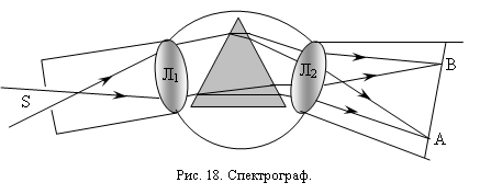
A device for photographing spectra is called a spectrograph.
The scheme of the spectrograph is shown in Fig. 18.
The radiation spectrum with a lens L2 focuses on a frosted glass AB, which when photographing is replaced with a photographic plate.
Camera
The most important parts of all devices are the camera, lens, device for focusing the lens, the viewfinder, the shutter in the tape drive mechanism. More advanced cameras are additionally equipped with an exposure meter or a built-in exposure meter, sync-contact, self-timer and other devices.
Depending on the type of photographic material used, all cameras are divided into film and laminar.
Depending on the viewfinder system and the method of focusing, the cameras are rangefinder, mirror (single and double lens) and with the simplest focusing on the distance scale.
Camera
Light-tight camera, which is also the camera body. The main components and mechanisms of the camera are mounted inside the camera, and their controls are located outside. The camera has a socket for attaching a lens. In modern small-format cameras, the camera has a rear flap. At the bottom of the camera there is a threaded socket for mounting the camera on a tripod.
Lens
It is the most important part of the camera and serves to create on the photosensitive layer of photographic film (photographic plate) the optical image of the photographed object. A lens consists of three or more lenses fixed in one metal frame. To reduce light losses due to reflection from the lens surfaces, the latter are covered with thin layers of various substances that reduce the light reflectance, that is, increase the transparency of the lens (there are single-layer coatings, but more often they are multi-layered). Such lenses are called enlightened.
The main parameters (characteristics) of the lens are: the focal length, the angular field of the image, the relative aperture and the resolving power.
Focal length .
Focal length ( f") determines the size of the image given by the lens, i.e., its scale or linear magnification. The greater the focal length, the larger the scale of the resulting image at the same distance from the subject. The majority of photo lenses have a fixed focal length, the value of which is indicated by Some cameras have lenses with variable focal length, which can be smoothly changed within certain limits. . Photo lenses, in which the focal length is approximately equal to the diagonal of the frame frame of the camera ( 1 k), called normal. If a f exceeds 1 k, such lenses are called long-focus lenses; Some lenses are called telephoto lenses. Lenses with focal length less than l kare called short focus.
The angular field of the lens in the space of images. Any lens forms an optical image within a certain circular in shape area called the image field. Image quality deteriorates with distance from the center of the field, i.e. from the point of intersection of the optical axis of the lens with the image plane. Therefore, when photographing, not the entire image field is used, but only its central zone, within which the image quality is satisfactory. The angle formed by the rays coming from the center of the exit pupil of the lens to the extreme points of the useful image field is called the angular field of the lens. The frame of the camera should be located inside the useful image field. Objectives whose angular field is in the range from 45 ° to 60 ° are called normal, with an angle greater than 60 °, wide-angle.
Relative aperture of the lens.
The relative aperture of the lens is the ratio of the diameter of its entrance pupil to the focal length, written in the form 1: K, where K is the f-number, indicating how many times the focal length of the lens is larger than the diameter of its entrance pupil. This number, called the f-number, is plotted on the lens aperture scale. The larger the relative aperture value, the higher the illumination of the optical image given by the lens, i.e., the greater the lens aperture ratio.
Resolving strength.
Resolving power (ability) L "is expressed by the maximum number of lines (strokes) per 1 mm in the optical image of a special test table (worlds). The higher the resolution of the lens, the greater the number of fine details is represented by the lens separately.
Aperture.
All filming lenses have a diaphragm - a mechanical device that serves to change their relative aperture. The diaphragm is usually placed between the lenses of the lens and contains several crescent-shaped petals, which form, overlapping each other, a roughly circular opening. The diameter of the hole varies in accordance with the established on the scale value of the diaphragm K. The petals are connected to a rotating ring mounted on the lens mount. There is an index on the ring, which is displaced when the ring is rotated relative to the scale, the divisions of which are calculated so that, when the ring is rotated one division, the illumination of the optical image formed by the lens changes twice. The process of changing the relative aperture of the lens is called a diaphragm. With a decrease in the relative aperture (increase in K) along with a decrease in the illumination of the optical image, the depth of the sharply depicted space increases.
Lenses designed for SLR cameras began to be made with the so-called “jumping” aperture. With such lenses, the aperture value is set in advance, but the light hole of the lens remains completely open. This allows you to focus the lens and set the boundaries of the image of the objects to be removed with a fully open aperture, that is, with its greatest illumination. When you press the shutter-release button of the camera immediately before it is triggered, the jumping diaphragm mechanism changes the light hole (usually abruptly under the action of a previously cocked spring), after which the photo gate is activated and then the diaphragm opens fully again (immediately or during the rewind of the film and the gate).
Movie camera
It is a projection system of the same type with the complication that the displayed pictures very quickly replace each other.
When designing, the result is usually a greatly enlarged image. For example, when designing a frame of motion picture with a size of 18x24 mm on a screen with dimensions of 3.6 x 4.8 m, the linear increase is 200, and the image area exceeds the area of the frame 40,000 times.
In order for the illumination of the object to be high and uniform, the correct selection of the condenser plays an important role. It would seem that the task of the condenser is to concentrate the light on the imaged object as much as possible. However, this is completely wrong. Attempts to "concentrate" the light on the object usually lead to the fact that the condenser gives it a greatly reduced image of the source. If the latter is not very large, then the object will be illuminated unevenly. In this case, part of the light flux will go past the projection lens, i.e. will not participate in the formation of the image on the screen. Choosing the right condenser makes it possible to avoid all the flaws. The condenser is installed in such a way that it gives an image of a small source C`C` on the lens L. The dimensions of the condenser are chosen so that the entire film S is evenly lit. The rays passing through any point of the transparency should then pass through the image of the light source C`C`. Consequently, they fall into the lens, and upon leaving it form an image of this point of the transparency on the screen.
In this way, the lens will give an image of the entire slide on the screen, which will correctly convey the distribution of light and dark on the slide.
For demonstration on the screen of opaque objects, for example, drawings and drawings made on paper, they are strongly illuminated from the side with lamps and mirrors and designed with a high-aperture lens.
Often used devices that have a dual system for the design of transparent and opaque objects. Such devices are called epidiascopes.
ConclusionThe practical significance of optics and its influence on other branches of knowledge are exceptionally great. The invention of the telescope and spectroscope revealed to the man the most amazing and richest world of phenomena occurring in the immense Universe. The invention of the microscope has revolutionized biology. Photography has helped and continues to help almost all branches of science. One of the most important elements of scientific equipment is the lens. Without it there would be no microscope, telescope, spectroscope, camera, film, television, etc. there would be no points, and many people who are over 50 years old would not have been able to read and do many of the works related to vision.
The field of phenomena studied by physical optics is very extensive. Optical phenomena are closely related to phenomena studied in other branches of physics, and optical research methods are among the most subtle and precise. Therefore, it is not surprising that for a long time optics played a leading role in a great many fundamental research and development of basic physical views. Suffice it to say that both the basic physical theories of the past century — the theory of relativity and the theory of quanta — were born and largely developed on the basis of optical research. The invention of lasers has opened up new tremendous opportunities not only in optics, but also in its applications in various branches of science and technology.
Bibliography.1. Artsybashev S.A. Physics - M .: Medgiz, 1950. - 511s.
2. Zhdanov L.S. Zhdanov G.L. Physics for secondary schools - Moscow: Nauka, 1981. - 560s.
3. Landsberg G.S. Optics - M .: Science, 1976. - 928s.
4. Landsberg G.S. Elementary textbook of physics. - M .: Science, 1986. - Vol. 3. - 656s.
5. Prokhorov A.M. Great Soviet Encyclopedia. - M .: Soviet Encyclopedia, 1974. - T.18. - 632s.
6. Sivukhin D.V. General course of physics: Optics - Moscow: Nauka, 1980. - 751c.
Optical device for photographing. Despite the wide variety of camera designs, the basic scheme is the same.
The camera is an opaque camera with a lens in the front wall and a device for placing photosensitive material (photographic plates or photographic films) in the back. The lens is used to obtain images of objects lying in front of him. It is characterized by aperture (relative aperture), the magnitude of which depends on the image on the photosensitive material. The magnitude of the aperture is expressed by a fraction, the numerator of which is equal to one, and the denominator - to any number, for example 1: 2; 1: 4, etc. The smaller the denominator, the greater the aperture ratio of the lens. Each lens is equipped with a diaphragm - a device that changes the relative aperture. It is intended to increase the depth of field zone (see The photo) and adjust the brightness of the image.
In each device (with the exception of devices for special purposes) there are: a device for focusing the lens, shutter and viewfinder. Focusing, or focusing on the sensitivity, is carried out by moving the lens relative to the photosensitive material or by moving the front lens of the lens. The shutter opens and closes the access of light through the lens to the photosensitive material. The viewfinder is designed to determine the boundaries of the image (photographed frame). In modern cameras, more devices are used to facilitate the shooting process: optical range finders, frame counters, self-trips, etc. 
Cameras are divided into plate (for shooting on photographic plates), film (for shooting on a reel film) and small format (for shooting on a 35-millimeter perforated film). Each of these types is divided into ordinary and SLR cameras. In the former, an image with the lens open is projected directly onto a photographic plate or photographic film (Fig. 1). In plate cameras of this type, focusing is carried out according to the image on frosted glass located perpendicular to the axis passing through the center of the lens. In film and small-format cameras (without frosted glass), this operation is performed on the meter scale or with the help of an optical range finder - a device that allows you to accurately determine the distance to the subject. For more advanced models of film and small-format cameras, range finders are built into the body of the device and mechanically connected to the lens mount (Fig. 2); This allows you to combine 2 operations (measuring the distance and setting the lens to sharpness) into one. This greatly simplifies and speeds up the shooting process. 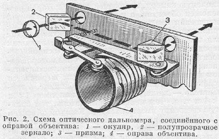
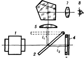
In SLR cameras, the rays that pass through the lens meet on their way a mirror installed inside the device at an angle of 45 ° to the axis of the lens. It throws the rays on the frosted glass, which is located in the upper part of the device (Fig. 3). 
When exposed, the mirror rises, giving access to the rays of light to the photographic material. The disadvantage of such devices is the need to sometimes make a sharp focus when zadiafragmirovannom lens, which reduces the brightness of the image and makes it difficult to tip. To eliminate this disadvantage, mirror devices provide two lenses that are mechanically interconnected and focused simultaneously: the top (target) on frosted glass, the bottom (working) - on the film plane (Fig. 4). 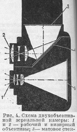
The described types of SLR cameras give an image on the frosted glass that is mirrored from left to right. which makes it difficult to shoot moving objects. To eliminate this drawback, a special prism (the so-called pentaprism with a roof) is inserted into the design of these devices, located above the ground glass and wrapping the image in two planes (Fig. 5). 
Thanks to this prism, the image is obtained straight and is located in a vertical plane, which allows you to follow it from the back of the apparatus.
From the film cameras industry of the USSR produces devices such as "Amateur" and "Moscow" of different models. The device type "Amateur" (mirror two-lens) gives images in 6 format cm H b cm. On one film fits 12 frames. It is equipped with a medium aperture lens. The shutter gives a shutter speed of 1/10 to 1/200 second. The new model of this device - “Amateur-2” (see Fig. 6 and inset) has a self-timer - a device that activates the shutter after 15 seconds. 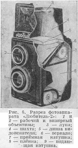
The device type "Moscow" gives images format 6 cm X 9 cm. On one film fits 8 frames. Its lens has a medium aperture. The shutter gives shutter speeds from 1 to X 1/250 seconds. The model of this device - “Moscow-5” (see fig. On the inset) has a lens of greater luminosity, self-timer and a device that allows you to take pictures in 6 format cm X 6 cm.
Of the small format cameras, the Smena camera has the simplest design. It is designed for 36 shots of size 24 mm X 36 mm and is equipped with a medium aperture lens and shutter, with exposures from 1/10 to 1/200 of a second. The latest model of this device - “Change-2” (see inset) has self-timer.
Small-format cameras such as "FED", "Sharp", "Zenith", "Kiev", "Leningrad" and "Start" (see the insert) are more complex and expensive. They differ from each other in degree of equipment. "Zenit" and "Start" - mirror devices with a wrapping prism.
The most convenient for amateur film cameras. Their advantages are: 1) a sufficiently large size of images that look great and without an increase (you can do without a magnifier); 2) the ability to charge and recharge in the light and 3) the ability to process the film in the tanks, which eliminates the need for a special dark room. Therefore, novice photo amateurs are recommended at first to use the device "Amateur", which, when skillfully applied, gives sharp pictures that can well withstand a significant increase.
"Optical devices"
1. Light filters
With the help of light filters, one part of the spectrum is usually separated from the others. This means that they are looking for a filter with a sharp absorption boundary from both the long-wavelength part of the spectrum and the short-wavelength part. Yellow or red filters have an absorption curve that decreases sharply in the short-wave part of the spectrum. With their help, you can cut off the shortwave part of the spectrum from almost any desired location. Filters of this kind are commercially available; You can order the desired absorption characteristic and get a filter that has the appropriate properties. It is much more difficult to obtain, using colored glass filters, an absorption curve that drops sharply in the long-wavelength part of the spectrum if there are high demands on the uniformity of glass. In this case, apply gelatin filters, colored organic dyes. Some guidelines for making such filters are given below.
A narrow region of the spectrum can be distinguished using a combination of Schott filters. For this purpose, it is very beneficial to use interference filters. They have a high degree of transparency and a narrow bandwidth. Using interference filters, it is very convenient to select certain lines from the line spectra of spectral lamps. By successively applying two or more interference filters of the same type, the missed background can be greatly reduced. Interference filters are fabricated with a maximum transmittance from l = 225 leagues to infrared. The manufacture of filters for the ultraviolet part of the spectrum is currently still associated with a number of difficulties. Recently, interference filters for the edges of the spectrum and individual lines have appeared on the market. By various combinations of such filters, any given spectral bandwidth can be obtained.
Interference filters are best purchased. Trying to make such a filter yourself does not make sense.
When using interference filters, one should keep in mind that their permeability varies with the direction of the incident rays. Interference filters in a stream of rays heat up a little, as they have very little absorption. Energy that does not pass through the filter is reflected. Therefore, it is necessary to take measures to eliminate the harmful effects of the reflected rays. Glass filters, which have a high absorption, under intense irradiation, become very hot, their absorption curve changes. The spectral boundary of the red filters shifts to the red with increasing temperature. In this regard, we mention that the transmission spectrum of a hot quartz flask of a high-pressure mercury lamp lies in the wavelength range\u003e 254 MMK.
Dyes are introduced into solutions of gelatin, which is dried on glass plates. Recipes 41 gelatinous filter published by Hodgmen. Below we give some of them. Glass plates must first be cleaned using sodium hydroxide solutions in water and potassium bichromate in sulfuric acid; gelatin is weighed, washed in a cold hearth and kneaded for an hour. Then take 300 grams of water for 20 g of dry gelatin, dissolve it at 40 ° C and filter. This gelatin solution is heated to 45 ° C, mixed with paint and pipetted onto a glass plate, cleaned as indicated; The plate is pre-installed horizontally and protected from dust. Two plates prepared in this way are glued together with Canadian balsam after drying.
Gelatin solution, if you add sugar to it, even better stick to the glass. Thymol is suitable for disinfecting the gelatinous solution: a small piece of this substance resembling camphor is thrown into the solution. “Chromic gelatin” can be used as the main substrate: 5 cm 3 of a 5% solution of chromic alum is added to 100 cm 3 of a 1% gelatin solution.
However, the production of a good filter still requires the known knowledge of the special properties of dyes and knowledge of certain techniques for working with them; it is necessary to think that E.J. Wall was right when he refused to make such color filters by himself. Therefore, in each case, it is necessary first of all to familiarize yourself in detail with the monographs on this subject of the indicated author or Weigert's monograph. With respect to all light filters in which the dye is dissolved in gelatin, there is a danger that their color will change in a few months or years, especially if the layer is glued with Canadian balm and if the filter has been exposed to light for a long time. Colored gelatin films are available for sale by a number of companies.
We can recommend the so-called monochromatic filters, which emit from the spectrum bands of almost the same width, adjacent to each other. There are two types of monochromatic filters: for wider and for narrower regions of the spectrum. If the transmission region narrows, then the maximum transmission value decreases by a few percent. Monochromatic filters can be successfully used to eliminate ambient light in simple monochromators.
For gray glasses, the transmission curve, in general, does not detect a dependence on the wavelength. Outside the red part, the degree of transparency in most cases increases dramatically. This property must be borne in mind when using such glasses, for example, in the form of a wedge as an attenuator in the spectral apparatus. The selectivity of a gray filter becomes important with very dense filters. Photographic gray filters are relatively little selective. Unfortunately, in most cases they scatter light a little, so that if these filters are used, the scattered rays can cause an additional light effect.
Much easier to make liquid filters. The coloring solution is poured into a bath with plane-parallel walls. The cylindrical glass vessels mentioned on p. 111 are very suitable for this purpose, at the ends of which plane-parallel plates are melted; from the side, a process is soldered into the vessel to fill it with liquid. The vessels of the Leibold are widely known; for them, as well as for making small ditches, see Weigert. Liquid filters from several well-defined layers placed one after the other can be made relatively simply with the help of appropriate cuvettes.
Colored inorganic salts are particularly suitable for filling liquid filters, since they exhibit complete light fastness.
The following directions are taken from Gibson’s work,
4400 A: 5% aqueous solution of potassium ferrocyanide,
5000 A: 6% aqueous solution of potassium dichromate, "
6000 A: plates of glass, stained with copper oxide, or of scar glass,
780: iodine in carbon disulfide,
8200 A: ebonite; the permeability of the plate with a thickness of 0.3 mm at 1 lx 37%, at 2 microns 61%.
Below are data on various infrared filters. These filters, as well as numerous dyes, investigated Merkelbach in the region from 0.6 to 2.8 microns.
Second class
Filters with a certain long-wavelength permeability limit: a layer of water 1 cm thick. Permeability at l = 1 micron 80%, at l = 1.5 Lek 0%.
Chains Photoelectric radiation detectors that use the external photoelectric effect phenomenon are called photoemission receivers. These include vacuum and gas-filled photocells, photomultipliers, electro-optical converters (EOPs) and some television transmitting tubes (dissector, iconoscope, superconoscope, ortikon, superorticon, etc.). Receivers with internal ...


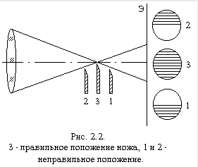

Heterogeneity has considerable depth. Interference-shadow device IAB-458 Interference-shadow device IAB-458 is designed for qualitative and quantitative research by the shadow method of heterogeneity of optically transparent media. The device implements the following research methods: luminous point, slit and knife, slit and thread, shear interferometry and holography. In fig. 2.4 ...
Optical instruments and their application briefly
Among the diseases and syndromes that Augmentin can cause
Should we believe dreams, and when they really are prophetic?
The benefits of nuts for women: types and norms of consumption
Modern methods of encoding alcoholism